I have had a long-time interest in 3D printing and 3D modeling, and regularly use it to solve problems I encounter in everyday life. The ability to easily prototype custom solutions without the need for expensive tools or labor-intensive processes is something that I’ve found incredibly useful since getting involved in the hobby. Here are a few of the designs that I particularly enjoyed working on.
Note: Some features on this page don’t work too well on mobile. For the best experience, view this page on a computer, or enable ‘Desktop Mode’ in your browser.
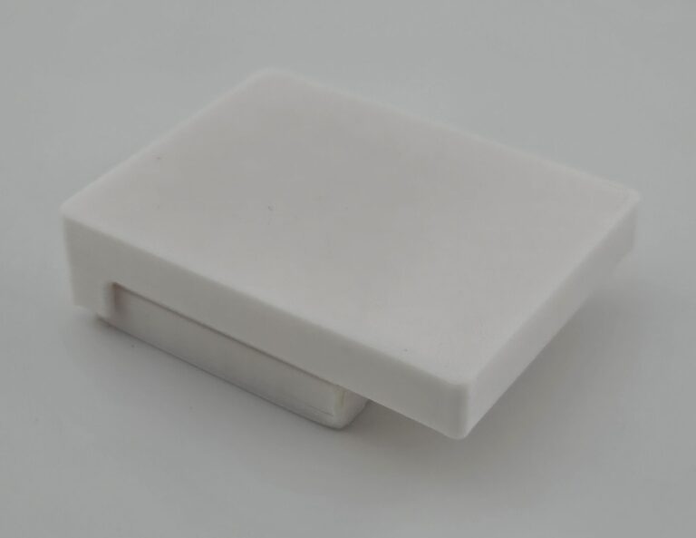
Wallet Storage Drawer
While I like the design of my current RFID-protected wallet, I was having issues with its capacity. I had a variety of cards that I felt I should carry on me, but didn’t necessarily need to take up the limited RFID-protected slots inside the wallet, like health insurance cards, gift cards, or my student ID. These cards were important enough, however, that I wouldn’t want to simply clip them on the outside where they could be damaged.
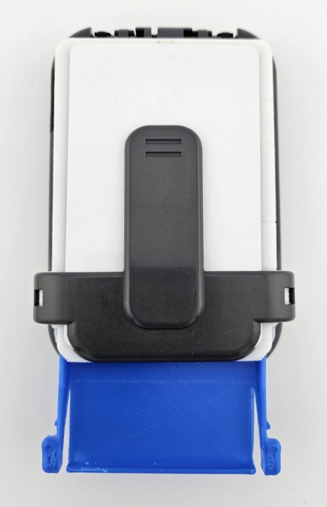
To resolve this, I designed and 3d printed a drawer attachment that securely affixes to the outside, and can safely keep additional cards inside. The assembly locks in place with the same mechanism used by the clip that came with the wallet, and the drawer housing includes a connection point so that the clip can still be used to store anything that needs to be accessed easily.
The drawer was able to effectively address the issue, and is something I still use on my wallet.
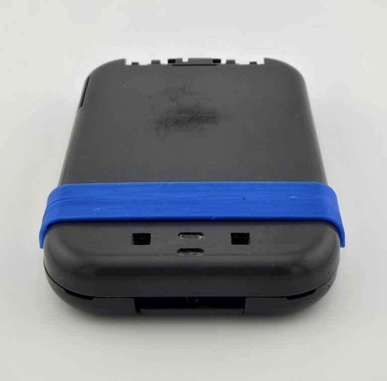
The first step for this project was figuring out how to attach the drawer to the outside of the wallet. The wallet came with a clip that would snap onto the wallet with a hook on each side that would hold on to two small holes on the casing. Additionally, though the specific attachment is no longer sold due to the manufacturer making new iterations of the wallet, a similar drawer attachment did exist that presumably used the same attachment mechanism. Based on that, I concluded that I simply needed to replicate that system and that would be sufficiently secure.
I accomplished this by making a test fit piece with just the clip based on just manual measurements of the wallet and clip attachment. From there, I fine-tuned the fit and tolerances with trial and error. Within a few iterations, I had a piece that firmly attached to the wallet, but could still be removed with some intentional effort.
The test piece was quite simple as it only needed to interface with the attachment mechanisms, and needed to be easy to print.
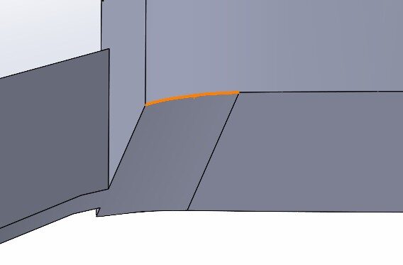
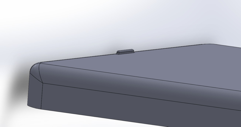
From there, the original plan for the housing was to basically just take that test piece, and add a box. There was, however, a slight wrinkle in that in order for the drawer housing’s interior to be wide enough for the walls of the drawer and a standard credit card, it would need to extend slightly beyond the flat face of the wallet. This may not have been a noticeable issue, but I nonetheless decided to add a slight raised portion at the appropriate edges to follow the contour of the wallet. (The change is only really visible in this 3d model viewer at specific angles, but is more visible in SOLIDWORKS.)
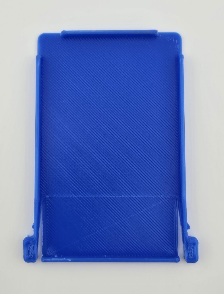
Next up was the drawer itself. It needed a way to securely lock in place once fully inserted so that it couldn’t accidentally fall out, with a mechanism to let the user easily pull it out when needed. My first thought was to have small bumps that would fit into grooves in the floor of the housing and latch when the drawer was fully inserted. These bumps would be on a simple compliant mechanism that let the user push them inwards to unlatch them.
Ultimately, I realized that not only was this idea overcomplicating things, it would make the drawer a nightmare to print, since the bumps on the bottom would prevent it from lying flat on the print bed.
As such, I decided to just put the locking mechanism on the side of the drawer with a simple cantilever snap-fit mechanism. This still required the compliant mechanism to unlatch it, but the implementation was much simpler.
To unlatch the drawer, the "arm" is pushed inwards so that the protruding edge can move past the notch without catching.
With that, the first iteration was completed, and could be printed for inspection. While the housing successfully attached to the wallet, and the drawer could be inserted and removed, there were improvements to be made. First, the mechanism to unlatch and remove the drawer needed fine tuning. Especially when the drawer had cards in it, limiting the range of motion for the “arms,” though it worked, it was not particularly smooth or reliable. Next, the drawer itself had a flaw: When cards were placed inside, there was no convenient way to remove them besides flipping over the whole drawer so they would fall out. Though this was a simple fix, as the solution was just removing walls on the corner of the drawer so that the corners of the cards could be accessed and lifted out.
While it's not impossible to remove the cards from this drawer, it requires either flipping it over and dumping everything out, or finding a place to get a fingernail between the cards and the side of the drawer, both of which are inconvenient options.
Once I got the basic utility worked out, there was one more feature I wanted to implement. As previously discussed, my wallet came with a clip attachment. This is particularly useful in cases where I need to have easy access to a card without having to open the wallet. As such, I wanted to have the option to attach that clip to the outside of the drawer housing.
Fortunately, this wasn’t too difficult. The dimensions of the attachment mechanism were already figured out, so it was just a matter of replicating that on the drawer housing. The tolerances still required fine tuning, but in this case, rather than designing a separate test piece, I just used the model directly, and stopped the print once the relevant portions were printed.
With that, the clip attached securely, and could hold an additional card for easy access. There was a slight issue in that a card held by the clip could slide too easily and didn’t feel secure, but that was solved by simply adding a small notch to prevent the card from sliding out of the clip unless it’s intentionally lifted.
Future Work
I’m quite happy with the design overall, but if I were to continue working on it, my priority would be looking for ways to reduce the bulk it adds to the wallet. Things like seeing if any parts can be slimmed down to make the overall assembly thinner without compromising the structure, or if nothing else, making extra drawers that simply have less capacity so that if I don’t need to carry as much, I can reduce the bulk accordingly.
Pen and Paper Keychain
In the past, I had encountered scenarios where I needed to pass along contact information, or write down a password, but didn’t have anything on hand to do so.
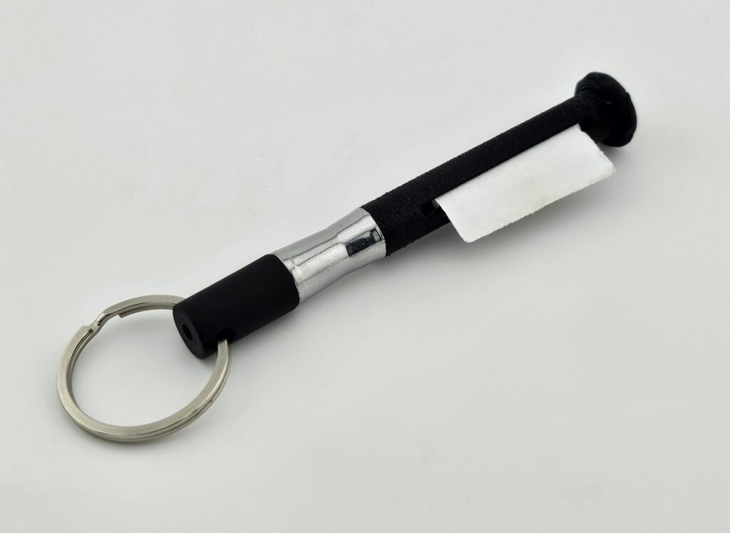
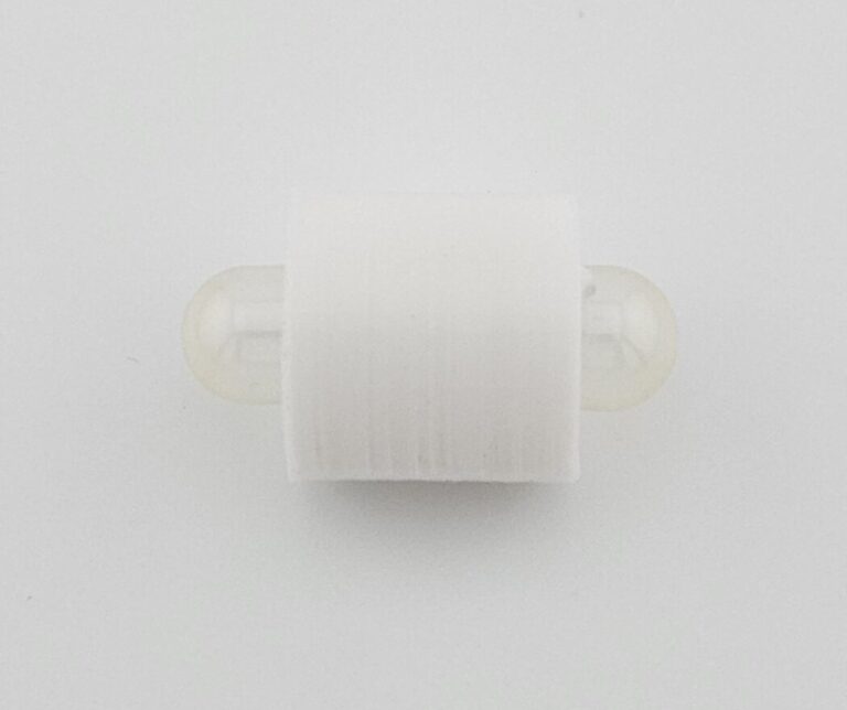
To address this, I developed a small pen with a scroll of paper stored inside that can go on a keychain. For the design, I took an existing pen keychain, and modified it to include a scroll of paper inside, which can be twisted using the knob on the top. A slot cut in the side of the pen then allows the paper to feed out where the necessary amount can be torn off and written on.
The design is a useful addition to my keyring, and is good to have on hand in case I need it.
I was honestly surprised that this concept wasn’t something that was already made and sold online, because while I’ve seen pens with a paper scroll stored inside, and I’ve seen keychain pens, I couldn’t find anything that just combined those two concepts.
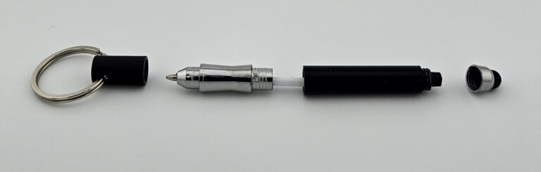
So to make my own version, I first started with just finding a commercially available keychain pen so that I could use as a base for the ink cartridge (which can’t be 3d printed obviously) and the pen cap (since trying to have such a precise fit would be challenging to 3d print. The pen I settled on using as a base was the one found here: https://www.amazon.com/dp/B08GSC39XF
The fact that the snap-on cap mechanism could be unscrewed, and put on a new pen body was the primary reason I chose this to use as a base.
This option had a good mechanism of attaching to a keychain while being easily removable by just putting the keychain on the pen’s cap. Additionally, the pen was assembled in multiple pieces that could screw on or off, making it easy to replace parts as needed.
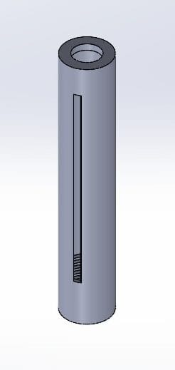
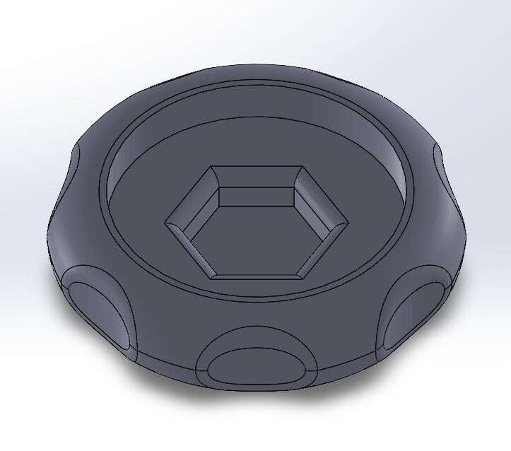
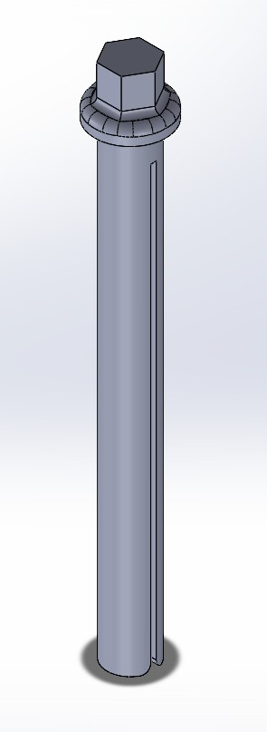
With the base pen decided on, I started on the initial design, which consisted of three parts: First, the paper scroll core, which would be a long cylinder that would be wrapped in paper, hollow so that the ink cartridge could fit inside. There would be a small slit that runs along the length of the core where the paper would be inserted and secured with tape, and the top would have a hexagonal shape to be inserted into the knob on the top. The knob would just be a circle with ridges to to grip, would fit over top of the pen body, and would have a small hexagonal hole for the top of the scroll core. Finally, in the original design, I designed the outer body, which would have a slot for the paper to be pushed out of, and threads to screw on to the part of the base pen that the cap snaps on to.
Pen Body
Knob
Paper Scroll Core
The design worked in theory, with a few caveats in practice. First, the end of the paper needed to be sticking out for it to be accessible. Turning the knob on the top was effective in retracting the paper, but not in forcing it out of the pen body, making the most effective way of doing so just pulling on the paper directly (which is only possible if there’s a little bit of it already outside to grab). Second, because of how thin some of these parts were, they were rather fragile, especially when aligned with the layer lines from the 3D printing process. This was particularly bad for the scroll core because it’s a long thin part that had to be printed vertically, however it was at least protected inside the pen body, so once it was installed, there was little risk of breaking. By contrast, the pen body itself posed an issue, as though it was certainly stronger than the scroll piece, it wasn’t strong enough to withstand the abuse of being on a keychain stuffed into a pocket.
In light of this, I decided the best way to move forward would be to modify the pen body that came with the pens I was using as a base. Fortunately the stylus portion of the pen body could be unscrewed and removed. In order to allow the scroll in the middle to be rotated using a knob on the top, I created a hole for the scroll core to go through, then to ensure it couldn’t fall out, I designed a cap that screwed on to where the stylus tip was removed and allowed the top of the core to go through to attach to the knob, without letting the rest through.
Version 1 Summary
Successes:
Mechanism functions as expected, allowing the retrieval of paper stored inside the pen
Final assembly is compact enough to be kept on a keychain
Areas for Improvement
Outer body of pen breaks too easily
Removing paper from pen body if it’s retracted too much is very difficult
No way to replace paper scroll once it runs out without reprinting everything
To begin addressing these issues, I decided the best way to move forward would be to modify the pen body that came with the pens I was using as a base. Fortunately the stylus portion of the pen body could be unscrewed and removed. In order to allow the scroll in the middle to be rotated using a knob on the top, I created a hole for the scroll core to go through, then to ensure it couldn’t fall out, I designed a cap that screwed on to where the stylus tip was removed and allowed the top of the core to go through to attach to the knob, without letting the rest through.
The parts in blue are glued together, while the cap in grey screws on to the top of the pen body where the stylus tip attaches. A hole is made in the top of the pen body large enough for the scroll core to pass through.
This revised design works significantly better, being resilient enough to keep on a keychain without major issue. Additionally, the cap that holds the scroll core in place being removable means when the paper scroll must be replaced, the modified pen body can be kept, and only the 3D printed parts need to be replaced. Breaking the empty scroll core or knob can even allow the cap to be kept.
Future Work
Though there are no critical issues with the current design, there are several places for improvement.
First, the flaw of the scroll core being fragile is still present. Though it’s not likely to be a problem during use, it does make printing and installation into the pen significantly more challenging, and also poses a problem when the paper needs to be refilled. The simplest way to fix this would just be to find an alternative method of making this piece without 3D printing. One idea would be using a thin straw, simply cutting a slit along it and having a part of the knob fit inside the pen body that it can be glued to.
Next, there’s the issue of it being difficult to remove the paper if there isn’t a portion already outside to pull. My plan to address this is two things: First, cutting the slot in the pen housing using a CNC router. This will allow the slot to be at a steeper angle, and closer to tangent with the scroll, which may make it easier for the paper to be pushed out of the pen by just turning the knob. Second, if that is not sufficient, I can cut a small slit that goes all the way through the top of the pen. This would make it so that when too much paper from the scroll is pulled inside the pen body, it can more easily be fixed. Since this option would require cutting through the threads on the top, it would require the cap piece to also go inside the slot to reinforce that portion and keep the threads properly aligned. Fortunately this is very doable, and in combination with fixing the issue with the core, may make it possible to combine the cap and knob into a single print-in-place design.
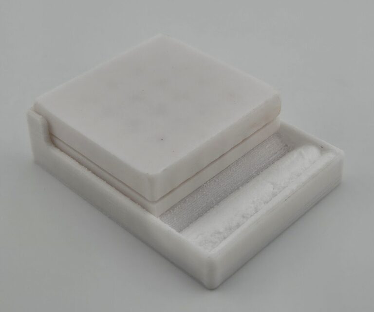
Capsule and Cap Filler
I take creatine supplements, specifically preferring to take them as capsules. When filling capsules normally, the body of the capsule is filled, and then the cap is just put on top, leaving a gap as the rounded top is unfilled. Normally this isn’t a big deal, however with creatine, the daily dose is high enough that it means taking a lot of capsules. Since the dosage doesn’t need to be especially precise, I prefer to reduce that number of capsules by also filling the cap of the capsule in order to ensure it is packed as densely as possible.
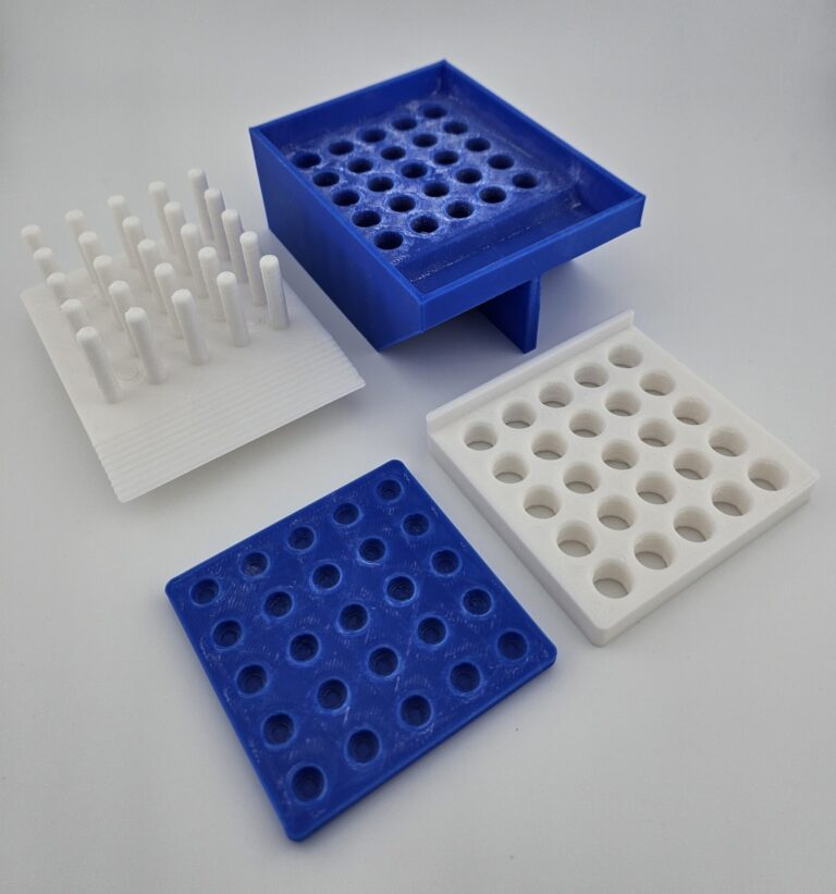
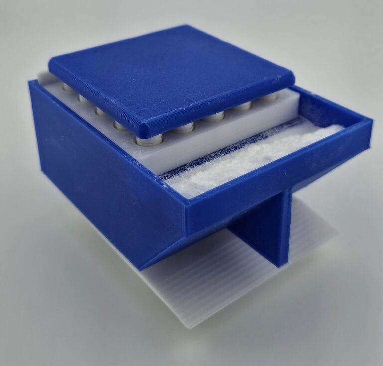
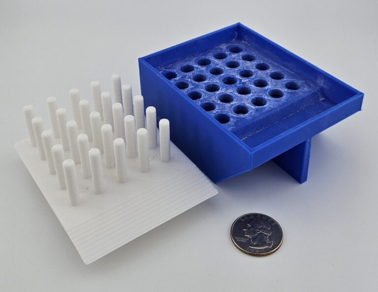
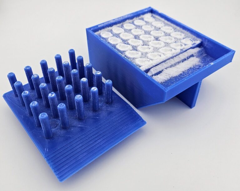
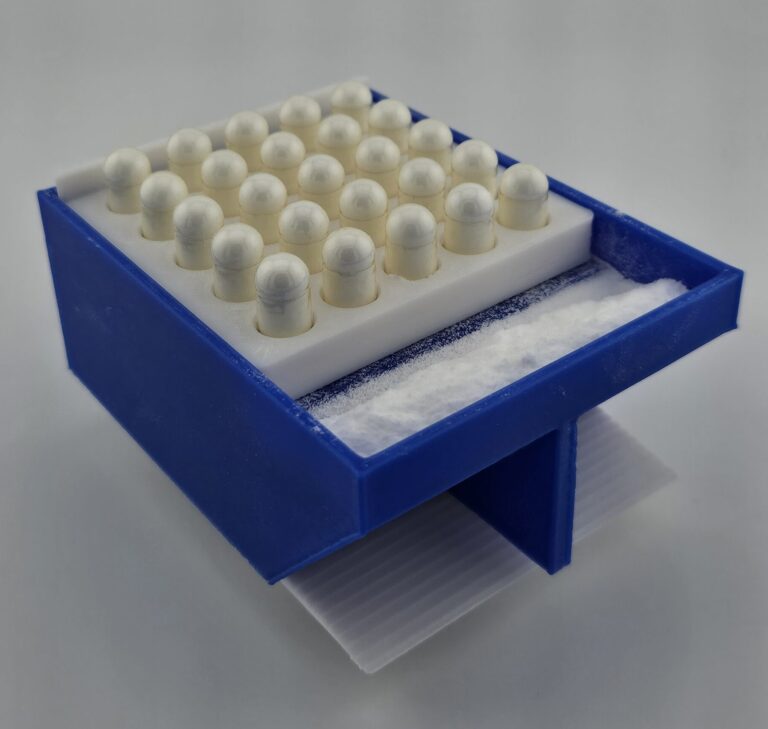
To make this process easier, I made this tool to fill capsules in this fashion in batches of 25. The tool is designed to both fill the capsule bodies, and measure out the correct volume of powder to fill the caps. That way, when the part is inserted in the bottom to push the capsule bodies up, it both fills the caps, and seals the cap onto the capsule body.
This process is far faster and easier than manually filling capsules by hand, especially in large quantities. Though a few capsules are damaged or destroyed if they don’t perfectly align with the caps, the current design only has a couple of failures per batch of 25, and the time saved is far more valuable than a few capsules that cost about a cent each.
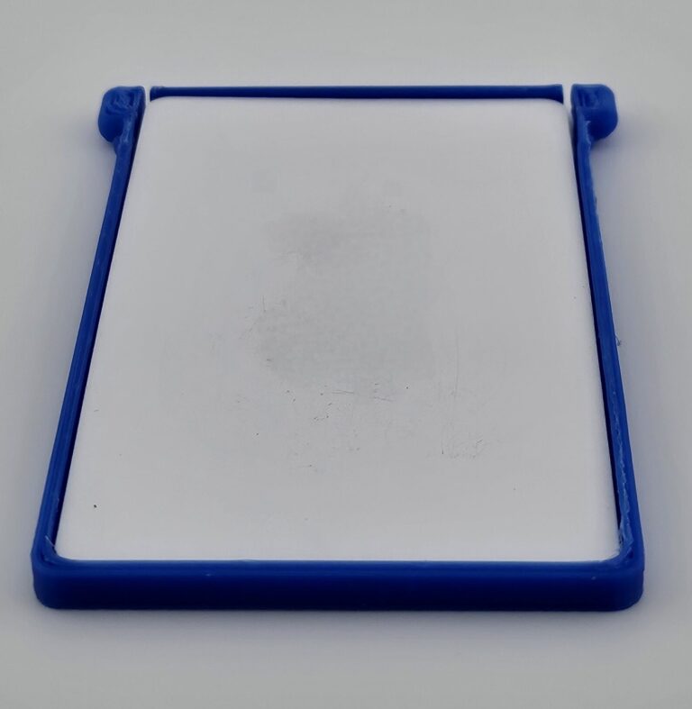
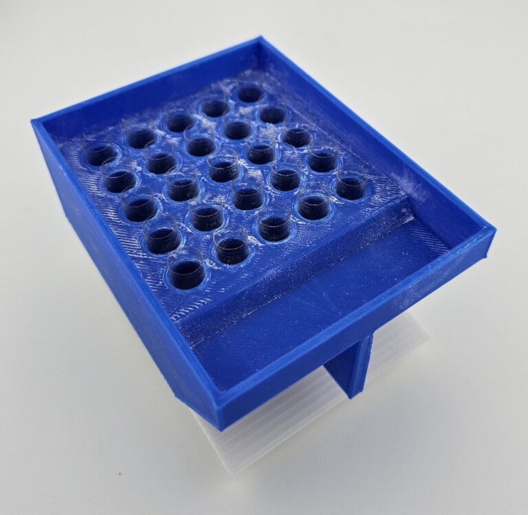
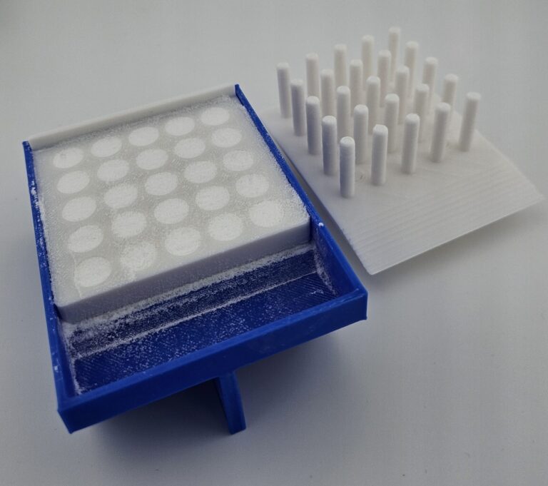
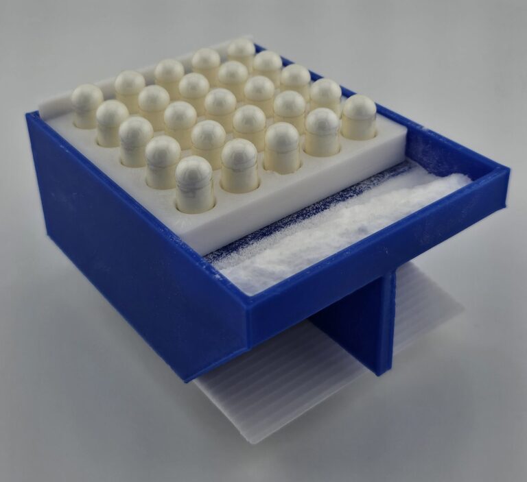
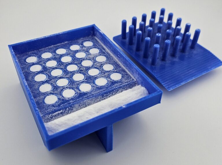
Capsule bodies are placed in each hole of the capsule filler
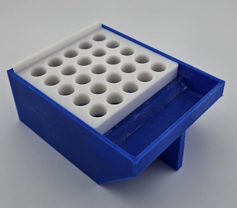
The capsule bodies are pressed into the holes and the cap holder is placed on top, aligning the holes with the ones on the capsule filler
Supplement powder (in this case, creatine) is poured into the holes and packed tightly with the multitool part.
The cap holder is removed, and the multitool is used to sweep the excess powder out of the way into the basin
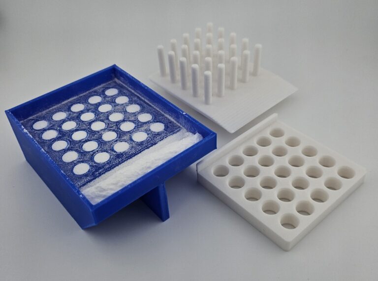
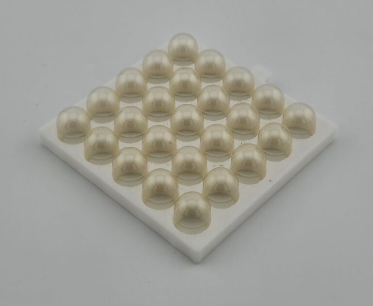
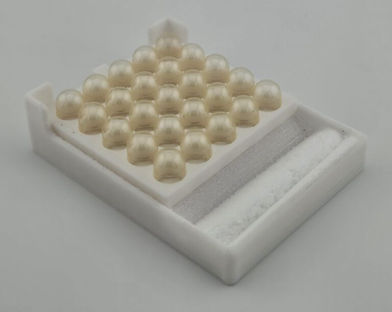
The cap holder is filled with caps, and placed over the holes in the capsule filler.
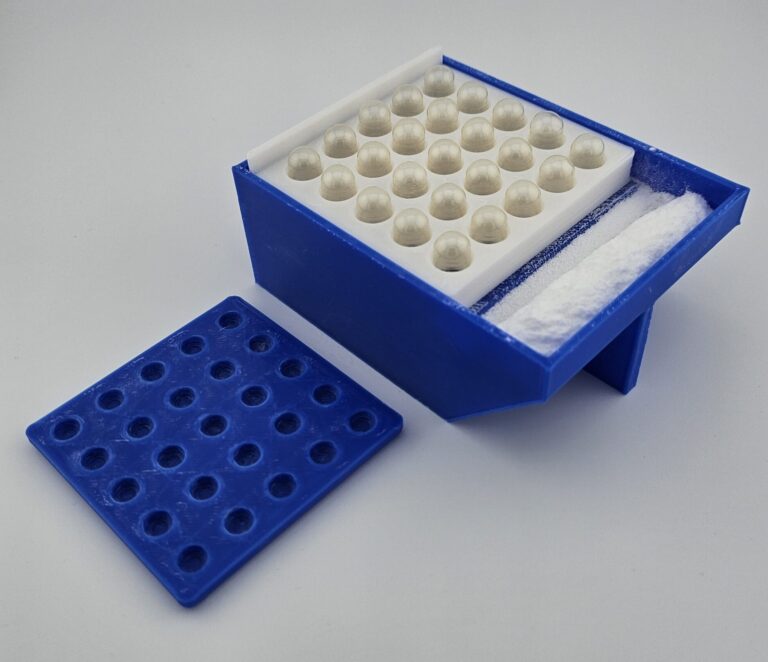
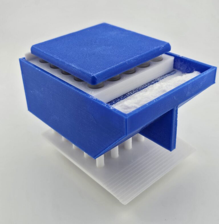
The cap cover is placed over the caps, and the pegs of the multitool are inserted into the bottom of the capsule filler
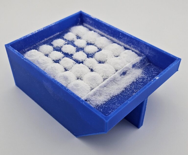
Pushing down on the top of the cap cover forces the assembly down onto the pegs on the multitool. This pushes the capsule bodies and premeasured excess powder up, into the capsule caps, sealing them together
This process fills batches of up to 25 capsules, ensuring the maximum milligrams of powder per capsule.
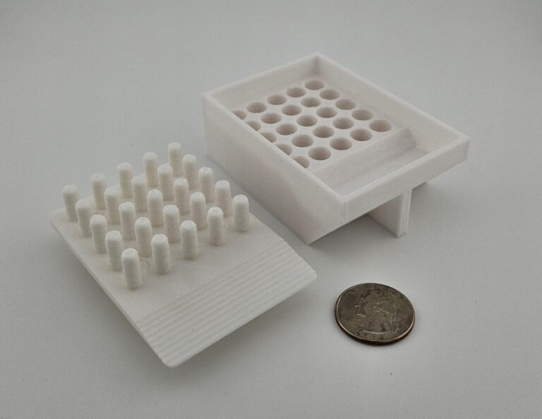
When I first started on this project, I was using an ordinary capsule filler design that I found online on Thingiverse. My goal was to create a separate design that would use the same multi-tool part to measure and fill the caps with creatine. The filled caps would then have to be individually placed on the filled capsule bodies.
For this design, one piece called the measuring tray had divots that measure out the volume of powder to fill the caps. The volume of these divots was determined first by calculation for a rough estimate, then by printing test pieces for one capsule at a time with varying volumes. The divot that fit the best was used on the part.
The other parts of the design was the cap holder and cap cover. The former had spaced holes that the caps could firmly fit into, spaced to line up with the divots on the other part. The latter was a similarly sized block with holes to cover the capsule caps so that all of the caps could be pressed down at the same time. These needed to be separate parts in order for the caps to be easily removeable once filled. These parts were also designed with small tabs to ensure proper positioning.
Measuring Tray
Cap Holder
Cap Cover
In order to use it, creatine was placed in the divots, and the pegs on the multi-tool part were used to compress it down. Excess was swept away using the same tool into a small basin. The capsule caps in the holder were placed opening-down over the divots, and the cover was placed over top. Next, the entire assembly was flipped over, both emptying the basin of excess creatine back to the jar, and allowing the creatine in the divots to fall into the caps. Repeatedly tapping the back of the assembly was typically necessary to ensure all the creatine released from the divots into the caps. From there, keeping it flipped over, the measuring tray and cap covers were removed, allowing the filled caps to be removed from the holder.
Creatine is placed on the measuring tray
The multitool part is used to pack the powder into the divots and sweep the excess into the basin
The cap holder is then placed over the divots
And the cap cover is placed over the caps
The entire assembly is then picked up so that the powder in the basin can be dumped back into its container, and then the assembly is placed upside-down so that the powder can fall into the caps.
The measuring tray and cap cover are removed, allowing access to the filled caps
While this process worked and certainly made things easier than trying to do everything by hand, it definitely wasn’t ideal. The process was rather complex and still required manually putting each filled cap on top of each filled capsule body, which was time consuming. Additionally, when the multi-tool part compressed the creatine into the divots, the pegs would disrupt the surface, and though it could be smoothed over, the powder that fills in the imprints of the pegs wouldn’t be as tightly compressed, and that would make the measurements inconsistent such that the caps wouldn’t have the right amount of powder.
Version 1 Summary
Successes:
Significantly faster than individually filling by hand
Method works pretty reliably
Areas for Improvement
Compressing the powder makes the volume inconsistent
Individually sealing caps to bodies is still inconvenient
Process for using cap filler is a bit complicated
Fortunately, the next iteration would be able to improve upon the successes while addressing the areas for improvement.
The basic concept would be that the capsule body would be filled, and the appropriate volume of powder for the cap would be measured at the same time, in the same slot. Using some test prints, I was able to determine how much deeper the hole for the capsule body would need to be in order for the extra powder to be the correct amount. From there, if the capsule was positioned correctly above the hole, the capsule body could be pushed up from below (as per the original Thingiverse design), pushing the extra creatine into the cap along with the capsule body in order to seal it.
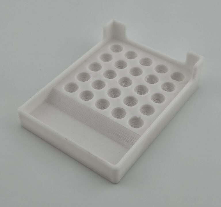
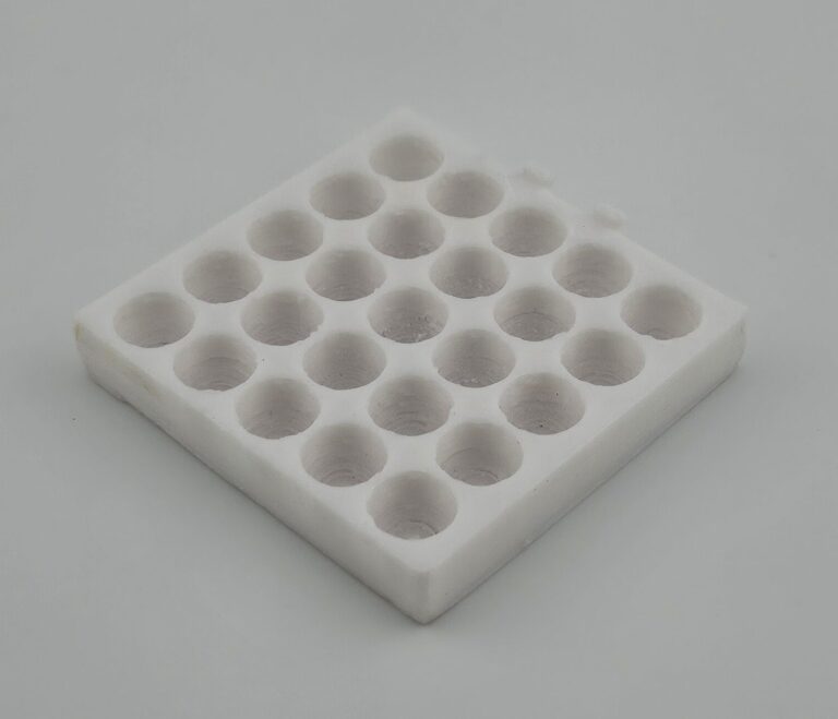
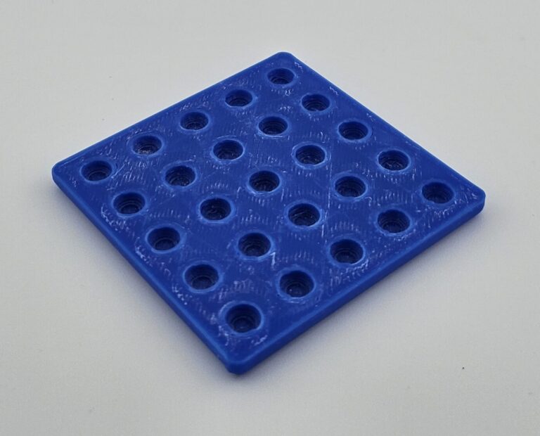
For this design, I remade everything from scratch, starting with similar design as the original Thingiverse capsule filler, but with a few notable modifications. First, as discussed, making the holes deeper to measure out the additional powder. Second I added more space between the bottom of the capsule body holder and where the capsules would sit. (This improvement to the original design makes it significantly easier to align the pegs on the multitool into place when pushing the capsules up, as it ensures there are actually holes for the pegs to be inserted into, compared to the original design, where the bottom of the capsules were fairly flush with the holes, forcing the user to visually line them up, rather than being able to do it by feel.) The holes for the capsules were also spaced further apart to make the filled capsules easier to remove.
The multitool part was also had effectively the same design, just with longer pegs since in this design, the capsule bodies need to be pushed up a greater distance. The little handle pieces, I just used the design made by the original Thingiverse creator. If it ain’t broke, don’t fix it.
Thingiverse Design
Improved Version
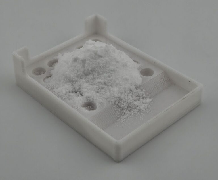
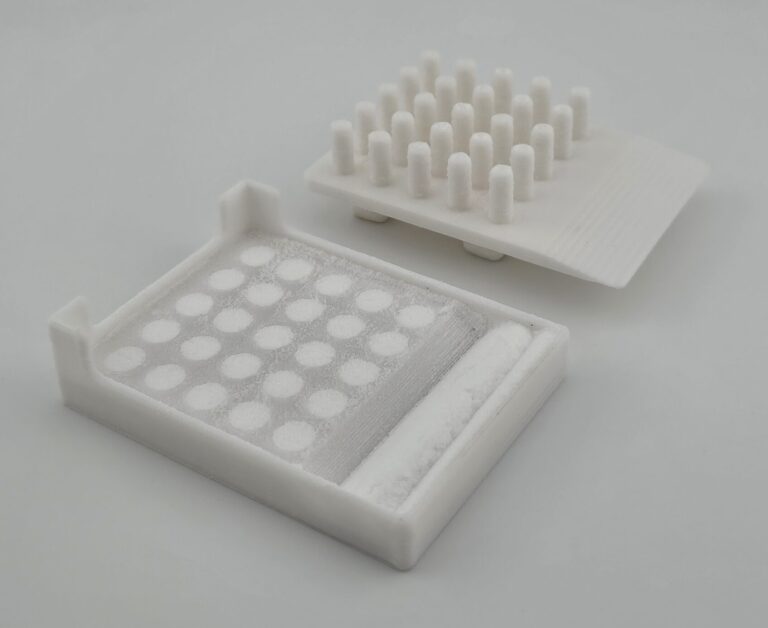
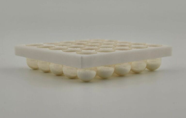
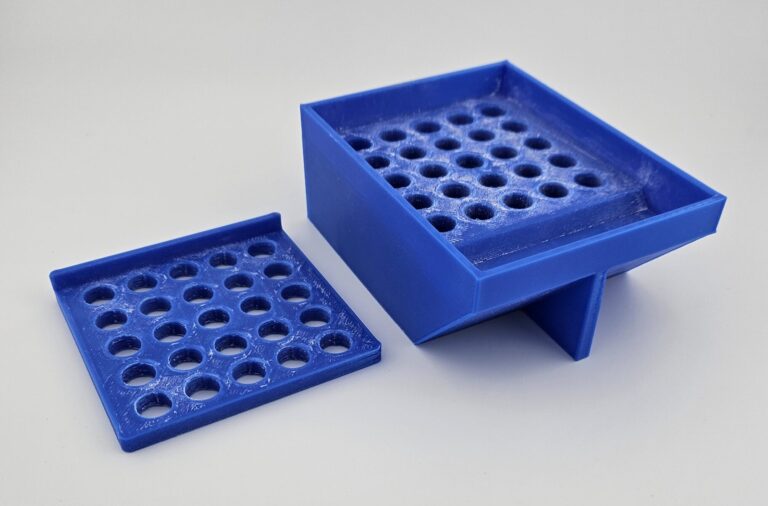
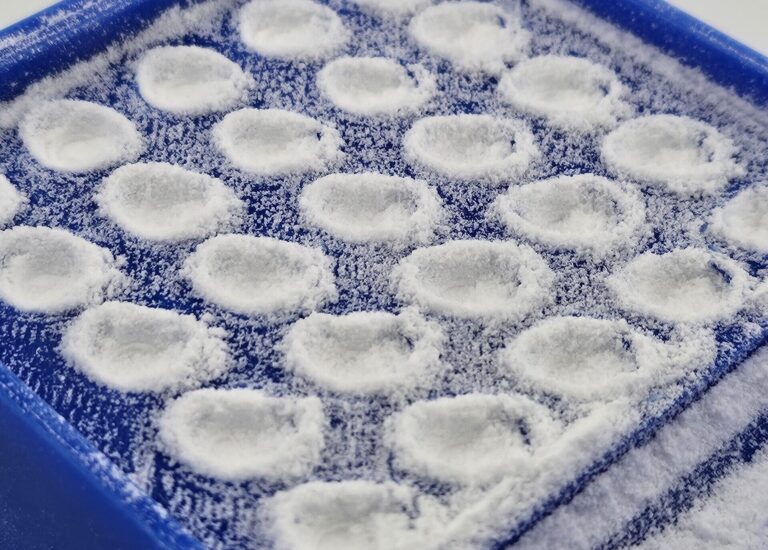
Next was the capsule cap holder. This part was designed to server two purposes; first, obviously, holding the capsule caps in place, and second addressing the issue of the multitool disrupting the surface and throwing off the measurements. The idea is that by placing the part (without caps in it) over the holes in the tray for the capsule bodies before filling it, it creates a “disposable” top surface. The powder can be densely packed, and the surface can get disrupted, but once the cap holder part is removed, it’s all just excess that gets swept away, leaving uniformly packed creatine in the holder itself.
On the left is the cap holder, but in addition to holding the caps in place for capsule assembly, it serves a secondary purpose while filling the capsule bodies
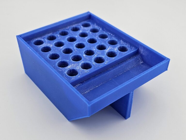
It is placed on top of the main body, aligning the holes
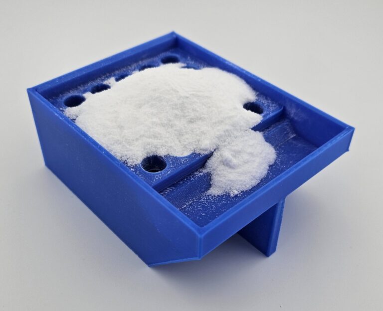
Creatine is placed on top to fill the holes
The multitool part is used to spread and pack the creatine into each hole
However, the pegs of the multitool create imprints in the powder when packing it. While this can be smoothed over again, the powder filling those imprints cannot be compressed to the same density without leaving more imprints
To address this, the cap holder part is simply removed. The imprints created by the multitool are now just part of the excess powder
That excess is then swept into the basin, leaving the holes filled with uniformly compressed powder
Finally was the cap cover. This serves a similar purpose to the first version, but was simplified by just having divots aligned with the capsule caps. Because in this design, the entire assembly no longer needs to be flipped over, covering the sides of the caps in the same way is not necessary.
Once all the parts were printed, the process was tested to mixed results. The process worked for some capsules, producing sealed densely packed capsules all at once, but others in the same batch were destroyed as a result of the capsule cap not lining up perfectly with the capsule body, causing one or both pieces of the capsule to tear or break as they were forced together. There were also some partial failures where the capsules were less severely damaged, probably being good enough if taken immediately, but risking coming apart if just dropped in a bag with the others.
Fortunately, the capsules are quite cheap, so I can easily tolerate a few getting broken as long as it saves time. Unfortunately with only about half of the capsules in each batch being a success, it wasn’t clear that all that much time was being saved, especially when the failures need to be manually emptied of the powder inside.
Version 2.1 Summary
Successes
Caps are sealed to capsule bodies in bulk
Volume of powder for cap is significantly more consistent
Operation is simpler
Areas for Improvement
A significant number of capsules are damaged or destroyed in the process. Removing and emptying these capsules is time consuming.
The initial theory on the cause for this issue was that the cap holder was compressing the cap slightly to hold it properly, and while this wouldn’t guarantee issues, it would reduce the margin of error in the cap being aligned with the body. I tried addressing this by just adjusting the tolerances, or adding a chamfer to the bottom of the cap filler so that the opening wouldn’t be compressed, but results either didn’t change, or got worse (respectively).
In light of this, it seemed more likely that the issue was caused by the fact that non-zero tolerances between the two different parts mean there’s some amount of wiggle-room in how the caps are positioned relative to the capsule bodies.
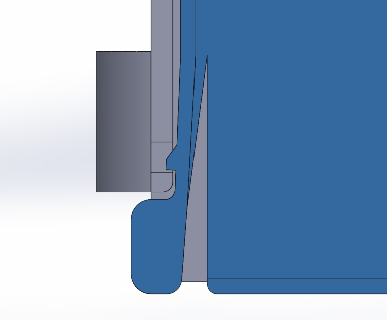
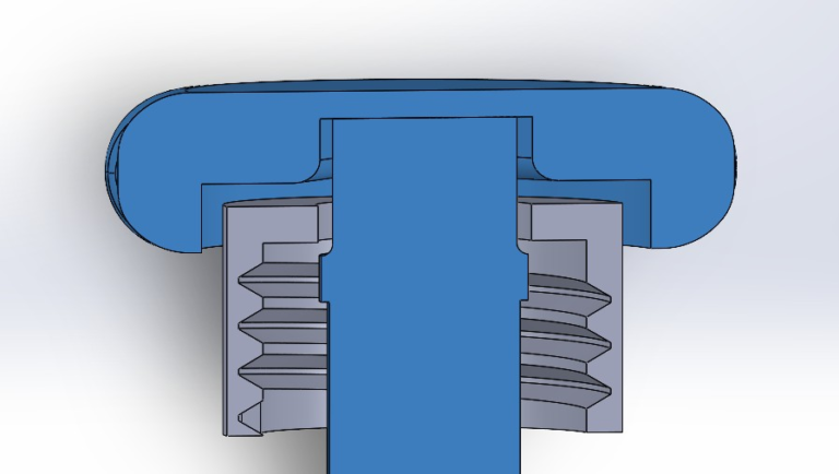
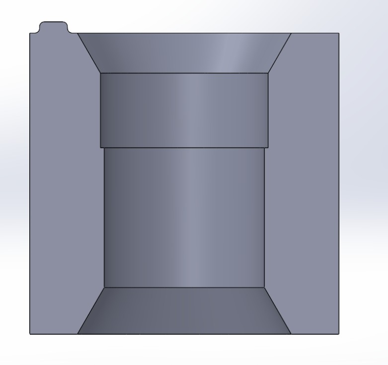
So the next idea was to have the final alignment of the capsule cap and body be done by a singular part, thus avoiding the issue of tolerances. The capsule cap is slightly wider than the capsule body (in order to fit over it), so the idea was to have a part with a small lip that would stop the capsule cap and hold it in place, with a slightly narrower hole that the capsule body could go through to place it directly in the center of the cap. Finally, a chamfer was added to the openings on either side to make it easier for the capsule pieces to be inserted.
Cutaway view of the test piece demonstrating the design. The small bump on the top left is to mark which side is for the cap vs the capsule body
I started off with a small scale test piece to try on just one capsule. After getting the sizing right to make sure that the capsule body could pass all the way through while the capsule cap was held in the proper position, it worked remarkably well.
The cap fit well into the slot, and as designed, could not be pushed in past a specific point, while the capsule body could go all the way through the test piece, ensuring it would fit into the cap's center
With that success, I was able to expand the concept, integrating it directly into the cap holder, and test it on a large scale. This also required lengthening the pegs on the multi-tool part due to the caps being held slightly farther from the capsule bodies.
The success rate increased dramatically, going from an average of 9 failures and 4 partial failures to just 2 failures, and 2 partial failures.
Especially with these improvements, this tool has made the process of filling capsules significantly faster and easier, and has been a very productive experience with iterative design.
Future Work
At this stage, I believe the basic concept of how to operate the capsule and cap filler has gotten about as easy as it can get. The main area for improvement left is just seeing if there’s any adjustment of tolerances to get the failure rate down even lower. I also may try printing existing designs with a smaller layer height in order to see if that improves things. It’s not entirely clear what exactly causes the failures to occur, since it worked quite reliably in the small scale tests, so that may warrant investigating if the issue persists.
Beyond that, the only other possible area for improvement that comes to mind would be improving portability of the tool. There are a few different parts, and while they’re not small enough to be easily lost, having an elegant way to keep everything together for storage could be convenient. This certainly isn’t urgent though.